Project Overview
A dual-servo control system using Arduino that allows precise control of two servo motors through analog inputs and includes LED feedback.
Project Description
This project implements a dual-servo control system using Arduino. It uses analog inputs from potentiometers to control the position of two servo motors independently. The system includes an LED indicator that provides visual feedback based on the vertical servo position.
Technical Implementation
The project uses the following components and technologies:
- Arduino Uno board
- Two servo motors
- Two potentiometers for analog control
- LED indicator
- Arduino Servo library
                                #include <Servo.h>

                                Servo servo1;
                                Servo servo2;

                                int ver;
                                int hor;
                                int swi;

                                void setup() {
                                  pinMode(A0, INPUT);
                                  pinMode(A1, INPUT);
                                  pinMode(12, INPUT);
                                  pinMode(3, OUTPUT);

                                  Serial.begin(9600);
                                  servo1.attach(10);
                                  servo2.attach(9);
                                }

                                void loop() {
                                  ver = analogRead(A0);
                                  hor = analogRead(A1);
                                  swi = digitalRead(12);
                                  Serial.print("X:");
                                  Serial.print(hor);
                                  Serial.print(" Y:");
                                  Serial.print(ver);
                                  Serial.print(" Switch:");
                                  Serial.println(swi);

                                  digitalWrite(3, swi); // LED control
                                  servo1.write(ver);
                                  servo2.write(hor);

                                  if (ver > 600 || ver < 400) {
                                    digitalWrite(3, HIGH);
                                  }
                                }
Key Features
- Dual servo motor control
- Analog input control using potentiometers
- LED feedback system
- Serial monitor output for debugging
- Threshold-based LED activation
Hardware Components
- Arduino Uno
- 2x Servo Motors
- 2x Potentiometers
- LED
- Jumper Wires
Project Simulation
Interact with the Arduino Servo Control simulation directly in your browser:
Project Video Demonstration
Circuit Diagram
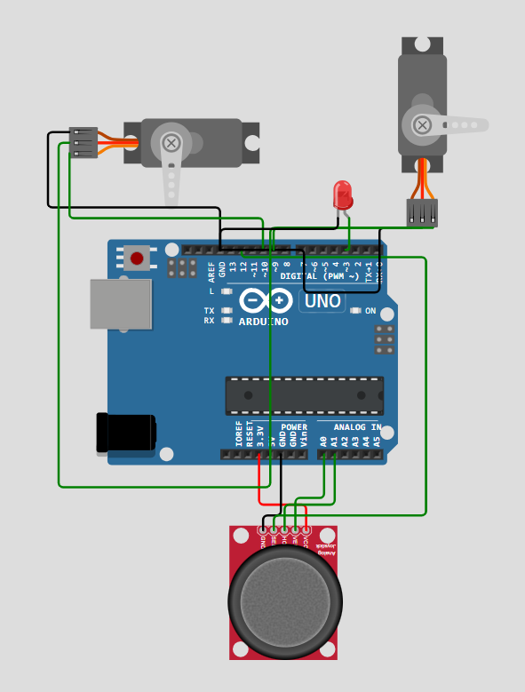
Circuit Connection
- Servo 1: Pin 10
- Servo 2: Pin 9
- Vertical Potentiometer: A0
- Horizontal Potentiometer: A1
- LED: Pin 3
Future Improvements
- Add smooth servo movement interpolation
- Implement position memory function
- Add wireless control capability